31.
Deformations of the structure during the construction
The F.E. calculations allowed evaluating the
deformations of the structure during the successive phases of the
construction.
The values of the horizontal and vertical deflections
(in cm) of the arch intradox are listed in the following table.
The values refer to seven different points of the
intradox, which are located at L/8, L/4, 3L/8, L/2, 5L/8, 3L/4, 7L/8.
The following deflections during the construction
phases were considered:
- deflection of the centering under the dead weight of the arch
voussoirs (to be evaluated by the contractor for the centering design)
- deflection of the arch, after the its completion, and under the dead
weight of the arch itself (obtained from the model which comprehends
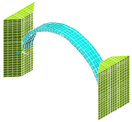
arch and abutments, see fig. 17)
- deflection of the structure formed by the arch, the wedges and the
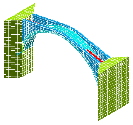
spandrels under their dead weights (fig. 18)
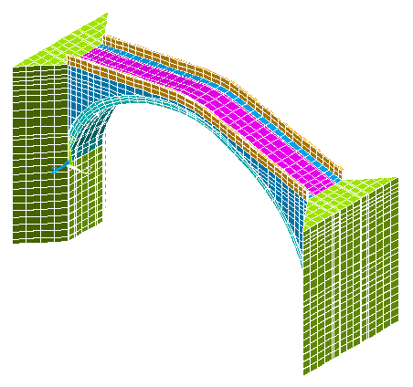
- deflection of the whole structure (fig. 19)
The values refer to each construction phase, so that
the final deflection is obtained summing all the contributions.
|
Construction phases |
|
L/8 |
L/4 |
3L/8 |
L/2 |
5L/8 |
6L/8 |
7L/8 |
|
Centering |
TO BE EVALUATED |
|
Abutments + arch |
Vertical |
-0.01 |
-0.11 |
-0.20 |
-0.22 |
-0.16 |
-0.06 |
+0.02 |
|
Horizontal |
-0.05 |
-0.01 |
+0.02 |
+0.03 |
+0.03 |
+0.06 |
+0.08 |
|
Abutments + arch +
wedge + spandrels |
Vertical |
-0.04 |
-0.09 |
-0.12 |
-0.12 |
-0.11 |
-0.08 |
-0.04 |
|
Horizontal |
+0.00 |
+0.01 |
+0.02 |
+0.00 |
-0.01 |
-0.01 |
+0.00 |
|
Bridge |
Vertical |
-0.05 |
-0.11 |
-0.15 |
-0.15 |
-0.14 |
-0.10 |
-0.05 |
|
Horizontal |
+0.00 |
+0.01 |
+0.02 |
+0.00 |
-0.01 |
-0.01 |
+0.00 |
In the paragraph 1.10, we suggested to dismantle the
centering only after the completion of all the work phases with the
exception of the construction of the paving and of the parapets. The
calculations of the deformations have been performed in safety considering
that the arch was dismantled just after its completion (to be more
precise, when the mortar setting takes place), as a consequence the actual
deformations will be not higher than the ones listed in the above table.
Schemes adopted in the calculation of the deformations

fig. 17 - Abutments
+ Arch

fig. 18 - Abutments + Arch +
Wedge + Spandrels

fig. 19 - Bridge
|