23. Locations
of the horizontal sections
The following figure shows
the locations (dashed lines) of the horizontal sections considered for the
vertical stresses sy.
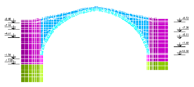
fig. 61 –
Levels of the horizontal sections considered for the graphical output of
the vertical stresses
24.
Stresses sy
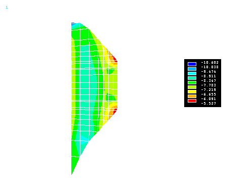
- Left abutment - Load combination no. 5C
Left abutment Horizontal
Section at 0 cm (load combination no. 5C)
- (sy
in kg / cm2)
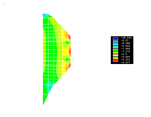
Left abutment Horizontal
Section at 150 cm (load combination no. 5C)
- (sy
in kg / cm2)
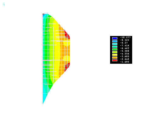
Left abutment Horizontal
Section at 487 cm (load combination no. 5C)
- (sy
in kg / cm2)
Left abutment Horizontal
Section at 716 cm (load combination no. 5C)
- (sy
in kg / cm2)
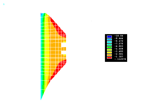
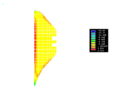
Left abutment Horizontal
Section at 846 cm (load combination no. 5C)
- (sy
in kg / cm2)
25.
Stresses sy
- Right abutment - Load combination no. 5C
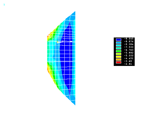
Right abutment Horizontal
Section at 0 cm (load combination no. 5C)
- (sy
in kg / cm2)
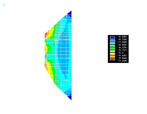
Right abutment Horizontal
Section at 190 cm (load combination no. 5C)
- (sy
in kg / cm2)
Right abutment Horizontal
Section at 511 cm (load combination no. 5C)
- (sy
in kg / cm2)
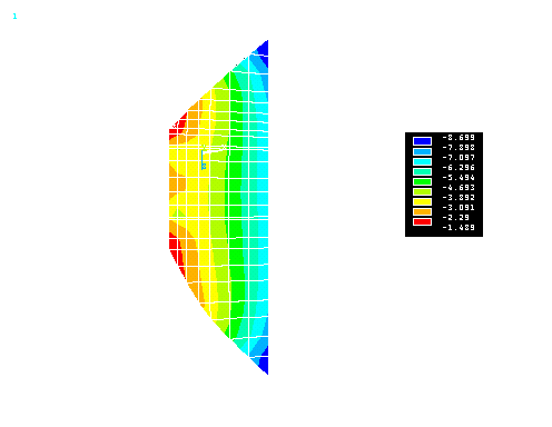
Right abutment Horizontal
Section at 706 cm (load combination no. 5C)
- (sy
in kg / cm2)
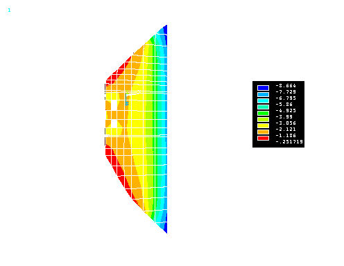
Right abutment Horizontal
Section at 872 cm (load combination no. 5C)
- (sy
in kg / cm2)
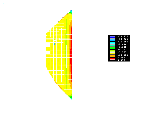
|