1.
Structural analysis and calculations
The structural calculations of Stari Most were
performed to evaluate the maximum stresses in the structure produced by
the design loads and the maximum deflections produced by the loads during
the working phases.
The following loads were considered: permanent loads,
live loads, thermal loads, accidental loads due to the flood and to the
earthquake.
The check of the structure against the earthquake
actions was made determining the peak acceleration which produces the
collapse of the structure.
In the fisrt part of this report some notes have been
taken on the basis of a preliminary and simplified geometry of the bridge,
then, in the second part, more accurate investigations have been performed
on the "most likely bridge shape".
2. The thrust line applied to the
arch of the Old Bridge of Mostar
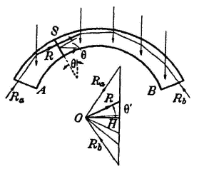
The thrust line of an arch is equivalent to the
pressure of the infinite number of funicular polygons joining the stresses
applied, whose first and last sides are represented by the springer
reactions Ra, and Rb.
This polygon is also referred to as polygon of
subsequent resultants because one of its generic sides represents the
straight line on which the resultant R of all the forces that precede it,
including also reaction Ra, acts. The value of R
comes instead from the projecting line corresponding to the polygon of
forces shown in the figure.

fig. 1 - the thrust line
Thus, the ordinary stress N and the shearing stress T
over a section S can be calculated by decomposing the resultant R,
referred to S, that follows the ordinary line and the line that runs in
parallel with the track of section S. The bending moment originates
instead from any of the following expressions:
M= R d= V do = H dv,
where d, do and dv, respectively
indicate the distances of the section of resultant R, of its vertical
component V and of its horizontal component H from barycenter G.
The thrust line offers an immediate view of the static
conditions of the arch that tends to improve with smaller deviations from
the geometrical axis and with the limited bending moments M. If it
coincided with the axis, each section would be subjected only to an
ordinary stress, because the stress would be uniformly divided along the
section and could therefore be equivalent to the safety load.
For this reason, you generally try and reach this
result by changing the form of the arch axis or, when it is possible, by
changing the thrust line through the distribution of the loads.
The sections appear completely compressed if the thrust
line is within the strip defined by the core points of all the sections
(third medium points of the rectangular section).
When all the loads are vertical, which occurs
frequently, the resultant R of any section S has an horizontal component H
that is constant and equivalent to the horizontal component (thrust) of
reactions Ra and Rb. In this case, it is easier to
calculate value M of a section S using the third expression of those given
above, thus taking as reference the horizontal component. Thus, the thrust
line of the arch axis, with vertical ordinates, is represented by diagram
M less factor H.
On three-hinge arches, the thrust line is statically
determined by the fact that the end and intermediate sides pass through
the three hinges. On two hinge arches, the ends must pass through the
hinges. In the previous examples and on restrained arches with rigid
constraints, the thrust line cannot coincide with the arch axis. As
stresses M and T would have no effect on all sections, the arch would be
deformed due to the ordinary stress that causes a reduction of length of
all the infinitesimal trunks ds, theoretically forming the frame. In other
words, this would produce a reduction in length of the chord that is
incompatible with the rigidity of the restraints.
By managing to apply appropriate stresses independent
from loads (for example by appropriately moving the restraints) it is
possible to confer an axial characteristic to thrust line of a specific
system of loads.
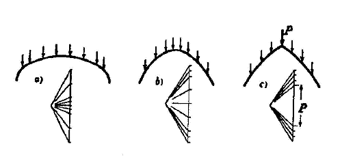
It is evident that the bending thrust line is more
significant in presence of higher loads, because the projecting lines of
the polygon of forces change direction more rapidly in these points. Thus,
with heavy loads on the reins, the thrust line appears as shown in Figure
2-a, while higher loads on the key stone produce a curve equivalent to the
one shown in Figure 2-b. If a significant load is concentrated on the key
stone, the thrust line is characterised by a cusp in the same point, as
shown in Figure 2-c.

fig. 2 - thrust line
shapes due to loads
The main consideration
suggested by Heyman's theory, underlines that the loss of stability of an
arch or of a vault is never a consequence of the breakage of material due
to exceeded resistance limits, but a result of the geometrical
configuration of the structure in relation to the funicular polygon
connected to the external loads. This means that from a safety point of
view it is not important to know the "true" thrust line. It is
sufficient to make sure that the arch thickness contains at least one
line. The above consideration can also be supported by Heyman's safe
theorem, that states that "the arch is safe, if it possible to
find a thrust line for the whole arch, both in balance conditions and with
loads applied, provided that is within the thickness of the arch".
Given these premises, it is evident that the problem
implies verifying the compliance with this requirement for one of the
three infinite funicular polygons connected to the system of loads and
acting on an arch restrained by the springing line.
This approach to the problem is the most plausible one,
also in consideration of the fact that the following issues were reported
for the examined arch:
- the arch is loaded by filling, which determine an unbalanced trend
of loads;
- the arch itself has a structural dissimetry. It is sufficient to
think that the arch of a circle with the best interpolation for the
left arcade is R = 1438 cm as opposed to R = 1427 for the right
arcade;
- these interpolated arches have a higher eccentricity as opposed to
the axis line by few tenths of centimetres.
In these conditions it is advisable to view the problem
in generic terms as suggested by Heyman's interpretation of the thrust
line.
For this purpose we have created several models with finite elements.
|