| ARCHITECTURAL ANALYSIS AND SURVEYS | English
|
|
5.5 Geometry Determination: 1982 survey analysis The 1982 survey is undoubtedly an important document for this work, it is the most precious document that we have at the moment, and it has been subjected to a series of different checks to verify its reliability. Unlikely of this photogrammetric survey held in the year 1982 we do not have all the data. If for instance we had the original photographic films of that survey now we could know exactly all the bridge dimensions in x,y,z co-ordinates with a predefined tolerance. What it is available of that survey is only the following:
Some of the above drawings were given by The Institute for Preservation of Cultural, Historical and Natural Heritage of Mostar – ICHM –, and some others were given by Conex company, involved in the drilling works. In both cases the real source of drawings hasn't been told.
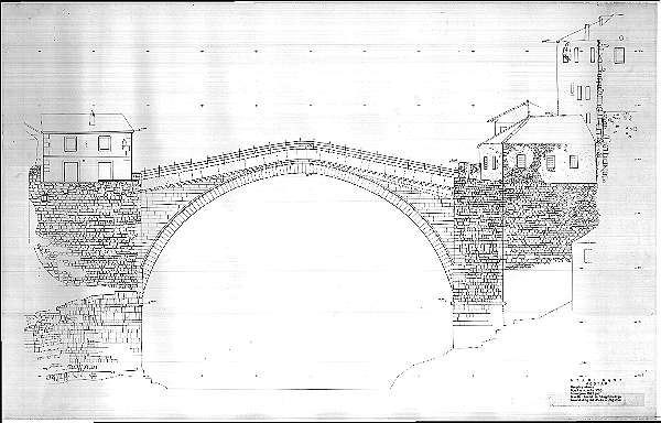
fig.07 - North elevation drawing
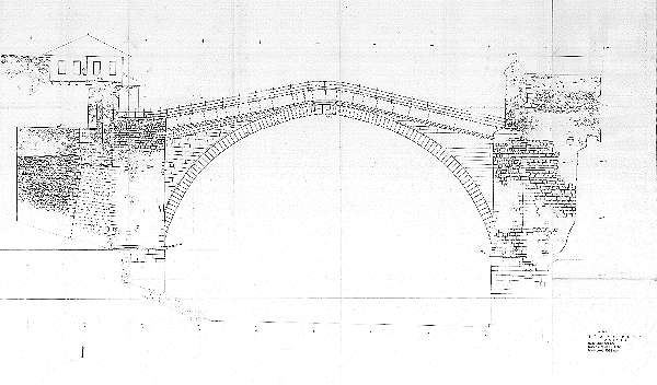
5.5.1 Quality parameters The quality level of the drawings, which are on the radex copies, is not suitable for this kind of works but it is absolutely the best source we now have either for the readability either for the deformations. The real problem of this survey is about the south elevation which has got a very poor quality since it appears to be a blueprint which didn't come very well since it is light and some areas are scarcely visible but the worst thing is that it was bent. for the aforesaid reasons the quality of this survey is not homogeneous and this has led to a more difficult analysis work.
fig.08 - South elevation drawing after retouching
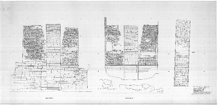
fig.09 - Intrados views The south elevations lines that were too light have been reinforced, while the ones that were not visible or that were not absolutely sure have been considered as lacks.
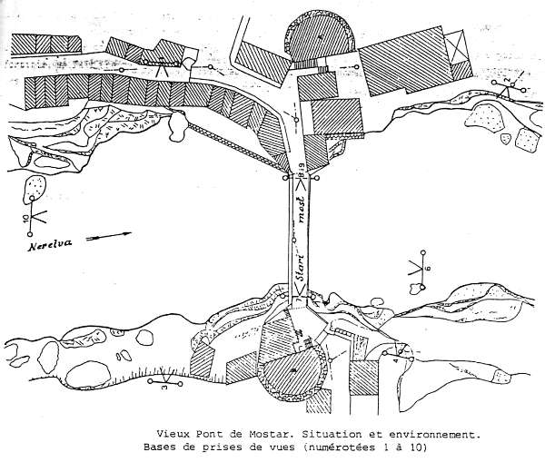
5.5.2 Reliability of the survey The survey seems to have been held by the University of Zagreb since on the drawing there is the following note: "Izradio: Zavod za fotogrametriju - Geodetskog fakulteta u Zagrebu". Both the fact that it is a photogrammetric survey and the fact that it has been held by an University Department are good evaluation data that may tell us about the quality, the accuracy and the reliability of the drawings. Moreover on a special report. (in French language) of unknown origins, General Engineering has found some more notes of sure interest for this work, this document is titled: "Relevés photogrammétriques de monuments Ottomans en Herzégovine et en Dalmatie", V.Donassy , Institut de Photogrammétrie Université de Zagreb (Yougoslavie) - Ponts de Mostar et d'Arslanagic', en Herzégovine. In the report there is written the following: "A la demande de l'Istitut régional pour la protection des monuments, le site a été relevé ŕ 1:200, par photogrammétrie aérienne, et le pont ŕ 1:50, par photogrammétrie terrestre, une attention spéciale étant portée aux parties basses et aux murs latéraux sur les deux rives. Pour les prises de vues, un photothéodolite Phototheo 19/1318 et una chambre universelle UMK 10/1318 (deux instruments de Carl Zeiss Jena) ont été utilisés. Certaines photographies ont été prises de la riviére, ŕ bord de radeaux spécialment construits (bases 6 et 10).
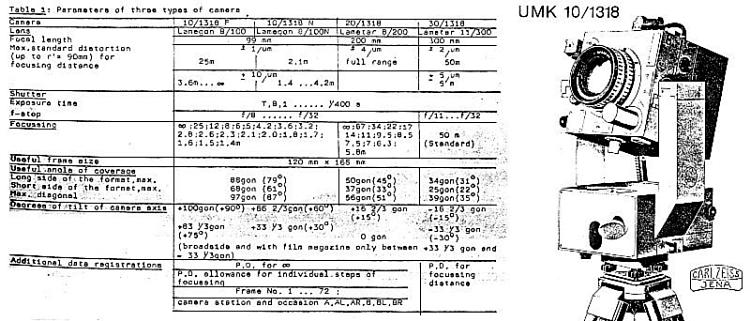
fig.10 - Vieux Pont de Mostar. Situation et environnement. La restitution, effectée sur un autographe Wild A.7, comporte une élévation de la face aval, une élévation de la face amont, des élévations des murs latéraux et une vue en plan de la voűte de l'arche." Following this note it has been inquired what is the type and quality of the instruments used for the task, and the results confirm that we are talking of high quality instruments with high level of accuracy: The camera UMK 10/1318 is characterised by the following technical parameters:
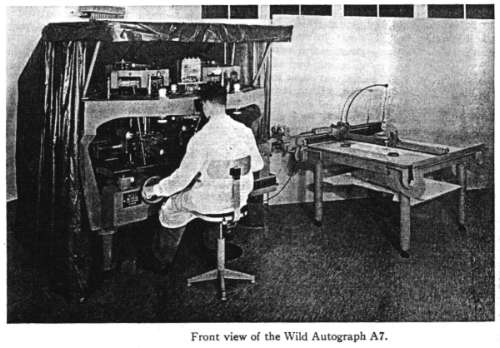
fig.11 - Technical data about the UMK 10/1318 The Wild A7 Autograph was presented to the public at the International Congress on Photogrammetry in Washington in 1952. It replaced the A5 Autograph and incorporated many improvements: although the instrument is ancient it is an high class instrument.
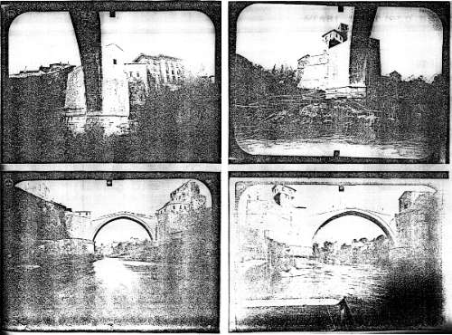
fig.12 - The Wild A7 autographer With all these findings we can be almost sure that in the year 1982 it was held a professional work with good instruments, but of course everything has been checked and verified anyway. Another interesting finding, that may be of help to understand all the involved parameters, is this ordinary copy (see following figure) of some of the shoots used for the photogrammetry work.
fig.13 - Copies of some of the shoots that have been probably used for the 1982 survey To a first examination it seems that the bridge is fairly small compared to the size of the pictures: many other elements have been included in the shoots like the abutments and the nearby buildings and towers. This has been probably caused by a technical requirements, (as it has been noticed by Giovanni Checcucci, one of General Engineering's technical expert in photogrammetric surveys), in fact to perform a good photogrammetric survey it is important to get couples of shoots that include many surveyed points located on various and distant x,y,z co-ordinates so that the stereo-model may be correctly generated. In the case of the bridge it was probably necessary to include all those nearby elements to have different surveyed points in the pictures: if a closer shoot were taken it would have been composed mostly by sky and river portions, where there are no possibility of taking reference points. But for the aforesaid reason it is possible that many small details, like some of the voussoirs joints, were not clearly visible in those pictures, because of the distance and because of the type of stones of the bridge, which are bright and reflect very much the sun light. Therefore we can say that the reliability of this survey is very high specially for all the most significant architectural elements, like curves, cornices, parapets, shapes and skyline, but may be affected by some inaccuracies on details like stone joints and voussoirs joints or any surface detail. Moreover we shouldn't forget that we have some copies of the original survey and not the original elaboration or the original film of the shoots: this is of course the most important unknown parameter that may mostly reduce the reliability of the drawings. It is really a big loos for the City of Mostar that those original shoots are not available for the present work also because it is most likely that, even if only three elaboration were produced in 1982, many more could be produced now with all the special and good pictures that had been taken on the on site survey. And it is also interesting to note that in Donassy's report there was written that special attention had been put on the low masonry walls and on the side walls but this can not be found in the final drawings where these elements are generally represented not in front views.
5.5.3 Digital acquisition - documents scanning All the drawings belonging to the 1982 survey have been acquired with a digital scanner wide enough to read the A0 size. The first acquisition has been done at the resolution of 300 dpi in grey-level; the final image sizes vary from 80 Mb to 130 Mb and it is a very important step that at least such important documentation had been filed in a digital format forever. For this reason the acquiring procedure have been extended also to the drawings belonging to the 1955 survey, and now everything has been recorded onto optical CD-R supports for long lasting archive. But the actual scope of the acquiring procedure is to have those documents in a digital format so that they may be inserted in computer systems for following elaboration.
5.5.4 Digital rotation-translation and scaling of drawings Drawings that have been acquired with the scanner may be a bit rotated, may be affected by some small deformations due to paper irregularities, and all these, are things that prevent from any computer metric processing and they have to be corrected. For this task can't be used an ordinary image processing software, but a purpose built software for metric control and for error mediation: thank to the small crosses that are drawn on the photogrammetric drawings, (called reference points and located on to an ideal grid of five meters step), it is possible to force those points numerically and the digital image will be corrected and referenced with a contemporary process of rotation, translation and scaling. Before this procedure is performed, the software gives to the operator important numerical values that quantify the necessary corrections that have to be applied, and from this numbers it is possible to understand the metric quality and reliability of the photogrammetric drawings or, in other words, how much deformed they are. The north survey, coming from a scan of a radex copy, has given very good results in this test: almost no scaling corrections were necessary and the drawing has been perfectly referenced to the cross points. The same can't be said for the south elevation which has given some problems in local areas, and this is due to the fact that the south elevation was a copy and it was bent. Deformations were so remarkable that making checks on the span of the bridge (which is a measure that we have surveyed), there were about seven centimetres of difference: the drawing was, therefore, about one and half millimetres shorter out of 30 centimetres, due to copy passages and bending; it may seems of no great importance but the intrados curve gets pretty different. To solve the above mentioned problem, a stretching of the digital drawing would not be absolutely acceptable for obvious reasons, so it has been used another source as check for that area: it was a digital acquisition of the same survey printed in 1:200 scale but the original paper support was not bent. Before doing this, for the south elevation, it has been done a check of reliability on the north elevation by comparing the correct digital acquisition (from the 1:50 drawing) with the related digital acquisition coming from the 1:200 drawing, and having perfect results on that test, the digital image of the south elevation has been processed giving also perfect results on the span measure: this way it has been possible to use the south elevation digital image (coming from 1:200 drawing) to make corrections. As it can be easily understood the low quality of drawings always represents a complicated problem to be solved.
5.5.5 From raster to vector in CAD system A raster image is a digital image composed by a matrix of numbers, where each number represents a dot with a colour or a grey level: the digital acquisitions of the survey drawings are raster images of the original paper support, that have been processed as described in the above paragraph. Raster digital image have been inserted in a CAD file trough a referencing procedure which enables to scale the image to the real model scale 1:1, so that the operator can measure the image in the computer system and can draw anything on it directly in real dimensions. Drawings in CAD are called vectorial drawings since they are defined not by a matrix of points, but by single points in x,y,z co-ordinates that may be linked by lines, polygons and so on. So, to study the bridge geometry, it has done a vectorial drawing in overlay to the raster digital image: this vectorial drawing, at the beginning, has traced the intrados line only, by putting a vertex on each voussoir joint. This way the intrados line has been defined by a "polyline" of 112 vertex, and setting the origin in the same point where it was fixed for the 1955 survey, the software trough a special command, can output all the numerical co-ordinates of the joints referred to the selected origin. And this, of course, has been done for both north and south elevation. |
|
|
CREDITS: Intellectual property of this report and of the design drawings is owned by General Engineering s.r.l.author of the text: arch. Manfredo Romeo – other contributes have been mentioned in related paragraphs © - General Engineering Workgroup - SOURCE: Final Design Report |
|