| ARCHITECTURAL ANALYSIS AND SURVEYS | English
|
|
5.4 Geometry determination: 1955 survey analysis Of what concern the survey held during the year 1955 we only have copies of the original drawings in 1:50 scale. We do not know how many copy passages these drawings have gone trough, and we do not know about the method and the survey systems and instruments that have been used. We do not know if these drawings are the full documentation of that work, or if they are part of a whole. The drawings may be listed as follows:
Some of the above drawings were given by The Institute for Preservation of Cultural, Historical and Natural Heritage of Mostar – ICHM –, and some others were given by Conex company, involved in the drilling works. In both cases the real source of drawings hasn't been told.
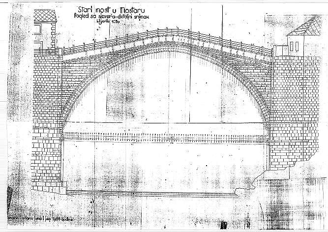
fig.01 - North elevation drawing
5.4.1 Quality parameters The quality of these drawings of the 1955 survey is very low since by making copies of a drawing the accuracy of the graphic measures gets worse; and drawings appears to be copied at least once; moreover some of these drawings are a mosaic of different copies which definitely doesn't allow any graphic check, or reliability. In many cases the readability is also very low, due to dark or light areas, and hand-written dimensions are, many times, so small that are not of easy interpretation. Although these copies appear to be ruined and bent they are precious anyway for the number of dimensions of every single stone of the elevations of the bridge.
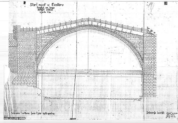
fig.02 - South elevation drawing
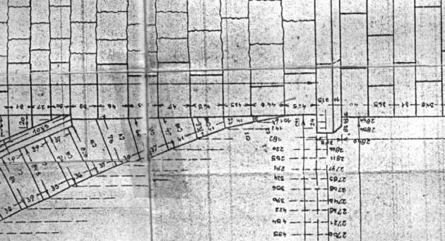
fig.03 - Detail showing the low quality of the drawing
5.4.2 Reliability of the survey Since the very low graphic level of the survey, it has been decided to use the numeric information of the dimensions to assemble again the original survey, and to gather from it the most reliable data on the bridge. This also because in technical drawings of the type there is a convention for which what really counts, (in case of differences among dimension and graphic measure), is the numeric value which is supposed to be unchanged from the on site survey. So reading all the numeric values we are supposed to be able to remount again the original graphic work done at the time in 1955 after the on site work. Another interesting matter, concerning the reliability parameter, is about the instruments and the way the 1955 survey was held. As long as we know, we can't say anything for sure, but analysing the way the measures are written on the drawing, and what dimensions have been taken, it seems that the survey was held mostly in a traditional way with no special instruments. If this hypothesis were true, the data coming from this survey may be assumed only for local and short distances, and not for difficult cases as the different height levels of the arch curvature from an horizontal line probably located on a provisional scaffolding. Anyhow for what concerns the bridge span it has been verified that the two dimensions of meters 28.71 (north side) and of meters 28.62 (south side) are correct: laser instruments have surveyed the same distance, which is a good thing since it is mostly on long distances that traditional surveys may lead to the highest inaccuracies.
5.4.3 Numeric check of the survey In both drawings of the elevations of the bridge there are two dimension systems: one is local, and is referred to each stone length, another one is somehow referred to global distances, and gives information about the bridge curvature. This second dimensioning system is on the bottom of the drawings and defines the bridge arch trough a simple X,Y co-ordinates starting from an origin located on one springer. This two dimensioning systems are related one to the other by a simple geometrical relationship, therefore it is possible to analyse differences and inaccuracies in the same survey. To understand this relation we name an arch point (in a connection of two adjoining voussoirs): P(x;y), and the following will be named P1(x1;y1) where the values of x and y are the ones taken from the global dimensioning system. Therefore the dx=x1-x and dy=y1-y; while the stone length at the intrados level will be: sqr(dx2+dy2); that can be compared with the value of the local dimension.
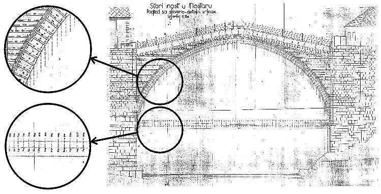
fig.04 - Local dimensions on each stone, and global dimensions in X,Y co-ordinates for arch curvature
fig.05 - geometric relationship between the two dimension systems: dx=x1-x and dy=y1-y
stone length = This test is quite important because it tells us about the accuracy of the work done in 1955, and it has been used also to cover data lacks in the drawing. As it was presumable, the numeric values of the dimensions of the 1955 survey are affected by an internal incoherence: the values of the x,y location of every single stone connection at the intrados, are sometimes in contrast with the local stone length been probably measured closely. Nevertheless incoherences are not so high, and this has brought to suppose that inaccuracies in the X,Y system are to be found as local events to be analysed each with the nearby ones, also because a difference which is not taken into consideration may brings to invalidate all the following metric data. Moreover all the x,y values dimensioned in the bottom of the elaboration are affected by the growing distances taken from the origin and from the reference level: so that an error of a 0.5-1% (which is the standard for this kind of surveys) on a distance of ten or twenty meters may brings a considerably high inaccuracy on the location of the stone connection and on the global geometry of the arch curve. |
|
|
CREDITS: Intellectual property of this report and of the design drawings is owned by General Engineering s.r.l.author of the text: arch. Manfredo Romeo – other contributes have been mentioned in related paragraphs © - General Engineering Workgroup - SOURCE: Final Design Report |
|