7.4 Stone cut procedure
Stone cut procedure is here globally referred to the work of preparation of
the stones for the bridge construction, actually it could be correctly subdivided in
different categories related to time and to types as here next explained:
| |
phase description |
conventional term |
1 |
quarrying of huge
blocks from the source site |
QY-blocks |
2 |
rough stone cut in
parallelepipeds + (qt) min 3 cm |
SC-rough |
3 |
final stone cut with
final shape and dimensions |
SC-final |
4 |
stone finishing and
adjusting |
SF-adjusting |
| |
type description |
conventional term |
1 |
Stari Most Stones -
Arch Stones |
SMS-A |
2 |
Stari Most Stones -
Bridge Stones |
SMS-B |
The above classification terms will be used in
following paragraphs to allow a better understanding of all the different issue which are
often referable to more phases at the time. A preliminary analysis of the main
peculiarities of the arch geometry analysis is here next exposed in order to gather the
reasons of the technical approach.
7.5 Main irregularities of the
archivolt - SMS-A
The most likely survey of the arch bridge, result of different ancient survey
comparing, and called here survey 2000, has revealed all the slightly imperfections that
were a proper characteristic of the monument. Geometrically speaking these variations may
be resumed as follows:
| |
main irregularity type |
additional note |
1 |
arch curves
irregularities (also from north to south) |
different north-south
span |
2 |
front face shape
variation |
all dimensions and
angles |
3 |
variation of height
above sea level |
north to south in arch
row |
4 |
different raising of
the rows |
north to south in arch
row |
5 |
size and rotation of
front face |
north to south in arch
row |
6 |
deviation from row plan |
for each row plan |
The above listed irregularities have been moreover studied, by the
use of numeric electronic charts and co-ordinates with special enquiries about range,
highest and lowest values, areas in the arch where these anomalies were more present and
by detail digital graphic comparing among north and south elevation. A more detailed
comment about each type is here next reported.
7.5.1 Arch curvature
irregularities
arch intrados and extrados curvatures have some local irregularities and
discontinuities that make the arch of an irregular shape definable only trough co-ordinate
points (for more details refer to geometry determination studies); moreover north
elevation curvature and south elevation one do not follow same deflections, same height
and do not even have the same length and span.
main curvature data |
(cm) |
| |
|
span north side |
2871 |
span south side |
2862 |
springer level east
abut |
0 |
springer level west
abut |
13 |
north elevation
intrados curve length |
4058 |
south elevation
intrados curve length |
4036 |
The relationship between north and south elevation
curvature points is mainly linked to the relative position of the origins of the
co-ordinate system of the curves; in other words, most of the observed anomalies, and
their possible quantification is all based on the position of the springer level points in
the space. The survey work has chosen, as working reference, both for south and north
elevation the east side as the origin (coherently with the 1955 survey). In the three
dimensional co-ordinate system the origin has been set on the north-east springer, and the
south east has brought the following:
origin shift |
X shift (cm) |
Y shift (cm) |
Z shift (cm) |
north-east |
0 |
0 |
0 |
south-east |
3.8 |
1 |
-395 |
where the height is represented by the Y
co-ordinate, and the thickness by the Z co-ordinate.
In the following figure it is shown a correct
projection of north side over south one to have a better view of the differences that we
have in the thickness of the archivolt.
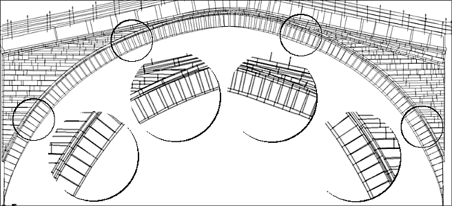
fig.1 - north and south elevation
correctly projected to underline differences
What it is important to
observe is that, (apart from local deflections), from the springer level to the arch
reins, and also further, there is a fairly good matching among north and south side: rows
are almost regular and deviations are low. It is mostly in the central portion of the arch
where north and south elevation do not match. It is probable that, during the original
construction, they had some settling of the wooden centering by the time they were loading
it (this could be the reason why we have highest differences on top); and probably they
tried to correct the settling of the centering by using wedges under the stone voussoirs
(traces of which have been noted by Mr. Bessac because of small steps among adjacent arch
stones). All the above matters anyhow are better analysed in the chapter about the
original design and construction method.
In order to complete this analysis of the main
anomalies of the intrados curves of the archivolt it is important to point out that the
position of north elevation and south elevation have been carefully analysed during the
geometrical study (refer to the proper chapter for detailed notes) and have been
determined to be parallel either for the 1982 survey results, either for a scarcely amount
of other notes about the eventual thickness variations of the bridge, which anyhow was
most likely to be quite regular for this peculiar matter.
Already from this preliminary overview it should be
clear that the archivolt is not a regular solid figure and that, for the stone cut, a
complex dimensioning system is required; this may be also confirmed by the fact that some
of the above variations may reach about 20 centimetres for homologous points along an arch
row. On the other side the requirements for a practical way of proceeding for the works
has led to design a simplified system of dimensioning which will allow, with a small
amount of dimensions, the performing of this irregular solid figure.
7.5.2 Front face shape variation
Front faces of the arch voussoirs
(elevation side) are commonly of a regular trapezoidal shape and all alike; it is not at
all the case of the Old Bridge of Mostar, where front faces of the voussoirs vary in
shape, size, dimensions and angles: only an average size is maintained along the archivolt
as shown in following figure.
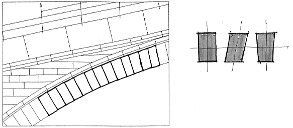
fig.2 - type of variations in front faces of voussoirs
7.5.3 Variation of height above
sea level
Each row of voussoirs, going from
north to south elevation, varies each height above sea level, of a quantity which is in a
range of cm 0-10 on about cm 395 of thickness. This irregularity is one of the most
difficult to be managed during the SC-final (final stone cut) and SC-adjusting (stone
finishing and adjusting) and requires to be analysed with observations held on the way the
bridge was originally assembled (see next paragraphs).
The above mentioned irregularity may have been caused by a settling and
a consequent lowering of the centering during the construction stage, and should not be
confused with local deflections that may have been caused by arch springers settling or
other similar happenings that have slightly changed the geometry of the arch in defined
spots.

fig.3 - variation of height of a single row in the bridge thickness
7.5.4 Different raising of the rows
During
the bridge construction, one of the parameter that was more difficult to be monitored was
the raising of the rows. Arch rows of voussoir have been assembled in a way that they do
not lie perfectly horizontal and parallel one to each other, and by the time that we get
on top (key stone level) this imperfection increases progressively mostly on one side.
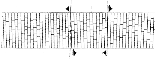
fig.4 - different raising of the
arch voussoirs rows on north and south elevation (plan view of the arch extrados)
This
irregularity of the rows may be caused by the fact that during the assembling procedure
was not so easy for a worker, standing over the centering, to gather the correct
progression at the same level either form north and south side. Another explanation of
this could have been that this irregularity easily increases by the time it is repeated
due to ordinary construction inaccuracies of stone sizes (see chapter about hypothesis on
the original construction method).
The range of this anomaly is the widest: cm 1-19 on about cm 395 of
thickness.
7.5.5 Size and rotation of front face
Undoubtedly
one of the most interesting findings of the geometrical observations has been the fact
that this kind of irregularity, (size of front face variation), is extremely low compared
to the others and we can say that voussoirs belonging to the same row were almost of the
same intrados dimension from north to south and in the bridge thickness: the gradual shift
is in a range of only cm 1-3.5 on about cm 395 of thickness, there are only a few cases
around the key stone in which exceptionally cm 11 are reached.

fig.5
- intrados size variation in a single row in the bridge thickness and front face rotation
All the above reveals
interesting notes about the construction technique used at the time: it is most likely in
fact that one of the construction rule that was followed during the load bearing arch
assembling was to choose for each row similar voussoir of same intrados length; so even if
adjacent rows could be different due to the natural availability of tenelija each row was
almost constant in its transversal thickness even if affected to a different raising (as
explained in previous paragraph). And it is only because of the raising anomaly that at
the key stone they were compelled to shape the last three rows gradually with a strong
size variation (until cm 11 in only one row) in order to recover the raising inaccuracy
and to close correctly the archivolt (see for more details chapter about hypothesis on the
original construction method). In the next paragraphs it will be explained how all these
observations will influence the SC-final and the SC-adjusting procedures.
Rotation of front face is also very low, but this irregularity is
much more difficult to be managed during the stone cut procedure and assembling, and even
small values may lead to very high incoherence. Rotation of front faces in the thickness
of the bridge archivolt is mostly a matter related to the intrados surface (extrados had
more construction imperfections and was not even smoothed), this is why rotation is
analysed in the following paragraph as a deviation from the row plan.
7.5.6 Deviation from row plan
The
geometrical analysis held on the ancient surveys (see related paragraphs) was mostly aimed
at finding all the co-ordinates of the connections joints of the arch curves on both north
and south elevations. Once the results of this inquiry have been related in 3d
co-ordinates each intrados row was delimited by four points: two of a voussoir of north
elevation, and the other two of the homologous voussoir belonging to the south elevation.
But from geometrical rules we know that one plan is defined by three different points in
the space, and four points may be not lie together on the same plan. So the model of the
archivolt had to be worked out facing this irregularity mostly for what concern the
intrados surface. Numerically it has been monitored for each intrados row plan how far it
was the fourth point from a plan that was perfectly matching three of the four points.
This anomaly has been defined as "deviation from row plan" and represents the
non planarity of every single intrados row, the range found is from cm 0 to cm 3.5 out of
cm 395 of thickness, luckily in most of the cases this anomaly is lower than cm 1. And
even if this type of monitoring gives the error to one point only, we should not forget
that even small values of this parameter may lead to a rotation of the stone face that if
not managed and planned will cause a very bad matching of adjacent rows.
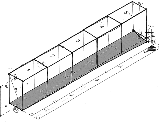
fig.6
- deviation from intrados row plan (equal to rotation of front faces)
7.6 Rough
stone cut - (SC-rough)
After the quarry of blocks
(QY-blocks) an intermediate cut is required in order to have smaller blocks: the closest
as possible to the final ones. This cut is here next called "rough stone cut"
(SC-rough) as before defined. As already pointed out, in the warnings of this chapter, it
has been agreed with PCU TA that a minimum tolerance of cm 3 was required in order to have
a margin, large enough, to perform the final stone cut (SC-final) and the possibility of
adjusting and finishing the surfaces (SF-adjusting).
It has to be pointed out clearly that the quarrying tolerance (qt) has
to be considered as an additional quantity to be added for each side of a length, which
means that globally the examined length will get six centimetres longer than its final
size once the stone cut (SC-final) has been performed.
Nevertheless, after a preliminary check, it was clear that, as far as
the arch stones (SMS-A) were concerned, it wouldn't have been possible to work out the
rough stones dimensions just by adding the quarrying tolerance to the final measures of
the stone faces and thickness. this mainly for two reasons:
1. Rough stone cut is meant to be an easy cut in parallelepiped blocks
with no irregularities and variations which are proper of the stone final cut.
2. Irregularities of height and raising in the rows actually require
wider rough block dimensions in order to contained wholly final blocks with the predefined
quarrying tolerance.
Of course all the above is referred to the arch stones (SMS-A) and not
to the bridge elements (SMS-B), where geometry is much easier and not linked to the vault
shape.
Figure n°7 of current page may give an easier explanation of the above
mentioned peculiarity:
section A of fig. 7 represents: plan view (bottom) and front
view (top) of a block (coloured in grey) in its final shape (after SC-final) which has got
a perfectly regular shape. In this hypothetical case no problem arise to determine the
shape of the block for the rough cut (SC-rough), which is drawn, as an outer profile, of
the previous one, respecting the tolerance (qt).
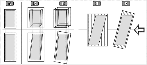
fig.7 - regular and irregular shaped
stone compared with the related rough block (SC-rough)
section B of fig. 7
represents: plan view (bottom) and front view (top) of a block (coloured in grey) in its
final shape (after SC-final) which has got an irregular shape due to different heights and
raising of the row. In this case it is clear, from the shape of the profile, that the
rough block has to be much wider compared to the dimensions of the final block (coloured
in grey).
section C of fig. 7 represents: the same of section B but with a
different profile of the rough stone block which is oriented in the direction of the
average axe of the final block. This way the rough block, being always a parallelepiped
may minimise either the use of stone either the stone final cut work (SC-final).
section D&E of fig. 7 represents: this two schemes
are respectively referred to section B and C and they point out, in an enlarged plan view,
the difference of the two approaches in matter of optimisation. Stripes are oriented as
the natural bedding of the lime stone and their gradient is compared to the acting forces
(arrow on the left). Of course best gradient would be for the one represented in section D
(=section B).
Conclusion of all the above notes is that the procedure to work out
dimensions of parallelepiped blocks (SC-rough) with the planned tolerance is not short and
may be not only based on the final dimensions of the final stones (SC-final).
In other words shape and volume are parameters that are strictly
related in this section of the design work, since an irregular shape, which has deviations
in all the directions, requires a larger volume, to be contained in it with a planned
margin, than a regular shaped parallelepiped (for which it is enough to increase its
dimensions of the desired "qt"). Being the irregularities of the arch stones
(SMS-A) in a wide range that may reach 10-20 centimetres, it is clear that, even if
distributed on three or more stones assembled in the same row, this quantity may get
higher than the "qt" with serious consequences and the impossibility of working
the final shaped stone out of the rough block.
7.6.1
Design procedure for rough stone cut
Design
procedure to determine dimensions of the parallelepiped blocks of the stone rough
(SC-rough) has been performed following different steps to better evaluate the most
desirable choice to adopt.
First all the dimensions of the stone cut (SC-final) of every single
row have been examined and compared in order to get the widest ones for the stone faces.
For every single block, this way, it has been determined the rectangular face shape by an
X and Y measure (maximum found in the row plus two times the quarrying tolerance).
Thickness has been examined for every single block depending on stone cut-final measure
and by adding two times the quarrying tolerance. All this has brought to a preliminary
calculation of the required volume of rough stone blocks even if it wouldn't have been
enough to contain all the final blocks (as before explained): this volume was about 190
cubic metres (for SMS-A only).
Subsequently all the co-ordinates of every single point of every single
final block have been calculated in order to manage the design by stone and not by rows
(approach by rows was not enough anymore for optimisation reasons). This calculation has
been performed trough mathematical calculations using as input data either the
co-ordinates of north and south faces, either the thickness dimensions of the different
block in a row (previously worked out with ancient surveys analysis). Co-ordinates of a
point that subdivides a segment with a predefined ratio are here next reported:
  
Where x1,y1,z1
are the 3d co-ordinates of a point on the north side, and x2,y2,z2
are the 3d co-ordinates of an homologous point on the south side; k is the thickness
of the stone (procedure has to be repeated as many times as the number of arch stones in
the examined row and for every front face point). Co-ordinate has been worked out with
calculation because no ancient survey data was available for this purpose. This work has
led to more than 10.000 new data.
The following step has been to analyse every single stone by means of
co-ordinates: all the co-ordinates were referred to a reference system which was oriented
coherently to the bridge elevation. For every stone all the co-ordinates have been
considered and it has been assumed the following:
X rough parallelepiped dimension = Xmax-Xmin+2qt;
Y rough parallelepiped dimension = Ymax-Ymin+2qt;
Z rough parallelepiped dimension = Zmax-Zmin+2qt.
The result of this procedure has brought to the scheme represented in
fig.7 (sections B&D) of previous page: rough blocks were big enough to contain the
final shape of the stones but were not optimised for construction material saving. The
difference was so remarkable that the total volume of rough blocks, worked out this way,
was +70% wider than the one previously calculated.
Since optimisation of stone was required and methodology of stone cut
would have been atypical compared to the ancient methodologies and to any other ever
adopted, design of stone cut has been performed following another mathematical and
geometrical device for calculation of rough stone block.
The final geometrical approach is the one represented in fig.7
(sections C&E) of previous page: the axe of the SC-rough parallelepiped has been
oriented along the average axe of the SC-final block in order to minimise the quantity of
wasted stone locating it mostly at the short edges of the block. This calculation has
required the use of a purpose built software routine, (see next paragraph), that, trough
rotations of a temporary reference system for each stone, has worked out all the required
measures in an automatic process.
The above system has given, as total amount of volume for the rough
stones, about 202 cubic metres, which is quite an acceptable value being about +7%
compared with the first estimation (that was moreover inadequate to cover the whole vault
in many cases). Moreover this design system will allow an easier procedure during the
other stages of stone cut with following facilities: smaller quantity of stone to be cut
for the SC-final (hand cut), more similar methodological procedure to the ancient followed
one. The only disadvantage which is foreseen is that stone bedding will have a small
gradient compared to the direction of the acting forces (see fig.7 section E); this
gradient will depend mostly on the different raising of the rows in the arch and will be
present only in the top portions of the vault: it has been evaluated, (after agreement
with PCU TA and stone expert), that it is negligible being not so wide and not a risk for
the durability and efficiency of the masonry.
7.6.2 Purpose built software routine for
rough stone cut
As
explained in previous paragraph, it has been necessary to process all the co-ordinate data
of the arch stones in their final design position in order to work out, with a
mathematical routine, the dimensions of the rough blocks. This routine works as here next
explained:
Each stone has been defined by its eight points in 3d co-ordinates, and
a new reference system has been defined to match the average axe of the examined block.
This new reference system has been rotated three times (on X, Y and Z) in order to be as
closest as possible to the spatial orientation of the blocks. Co-ordinates of the block
have been transformed in the new reference system and the dimensions of the rough
parallelepiped block as been determined as it has been done in the previous calculation:
X rough parallelepiped dimension = Xmax-Xmin+2qt;
Y rough parallelepiped dimension = Ymax-Ymin+2qt;
Z rough parallelepiped dimension = Zmax-Zmin+2qt.
(The software routine is here not reported)
The
above described procedure has been determined after many different approaches and
tentative; the process is not short and not even of easy management due to the amount of
data and compared to the ordinary architectural design procedures, but it is the best that
could be carried out to optimise stone wasting and to guarantee dimensions wide enough to
face all the geometrical anomalies.
7.6.3 Conclusion about the results of
the rough stone cut
Rough
stone cut (SC-rough) has given, as final result, three dimensions for each voussoir that
represent a parallelepiped block wide enough to contain the final shape of the designed
arch stone with a minimum margin of three centimetres. This way it will be possible to
perform rough cut easily with no care for any deviation or imperfections and with the use
of mechanical instruments for stone cut. A more accurate work during the design stage has
given the possibility of an easier process on site.
The above described procedure was required for what concern all the
arch stones (SMS-A), all the other bridge elements (SMS-B) had absolutely no similar
difficulties and it was possible to determine the SC-rough dimensions by choosing the
highest dimensions for each stone block and by adding two times (one per side) the
quarrying tolerance.
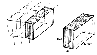
fig.8 – arch voussoir after
final cut and related rough cut block with bedding and code dimensions used in final
charts |