9.3 Lower cornice assemblage
Lower
cornices are located directly over the extrados of the load bearing arch, jutting out of
the vault profile to protect below structure. Lower cornices, being assembled on a curved
profile, required special care during the adjusting procedures and were, anyhow, anchored
to the arch with a mortar layer. On top side of the cornices, across the joints, it was
placed a single row of cramps approximately located along the longitudinal axe of the
stone elements.
assembling procedure:
- slots were carved over each stone block across the joints;
- for each joint two slots were carved (one per side) and joint was in the middle;
- between two twin-slots, located on the opposite sides of the joint, a trace was carved
to host the thickness of the cramp and to avoid any interference with the thickness of the
joints with above stone elements.
- once the cornices were correctly placed on site, the cramps could be applied by pouring
melted lead in the slots;
fig.17
– axonometric cut view showing the lower cornice; on the right: plan view and
axonometric scheme.
technical observations:
- slots were slightly widen at the bottom to avoid untying;
- slots were not polished but perfectly cleaned;
- slots were of rectangular section as the cramps edges that were supposed to be inserted;
- cramp positions depended only on the position of the joint to be connected;
- one row of cramps was provided for each joint;
- cramps were of rectangular section profile with extreme edges widen by hammering, to
avoid untying; cramps were made in hand forged iron;
criteria and
dimensions:
- cramps divided the cornice stone thickness in two equal
parts;
- the side cramps positioning criteria was quite simple: one cramp per joint of similar
dimensions;
- cramps sizes were slightly variable with no apparent criteria: most probably because of
ordinary constructive imperfections:
- cramp length: cm 30-35
- cramp hooking-edges length: cm 6-8
- cramp height: cm 4-5
- cramp height (widen edges by hammering): cm 6-7
- cramp thickness: cm 0.5-1
- cramp thickness (thinner edges by hammering): cm 0.5-0.8
- cramps were quite straight and hosted in the carved traces;
- dimensions of the carved traces were as the cramp profile to be settled in;
- dimensions of the slots were quite close to the cramps dimensions; of course the slot
opening should have been wide enough to allow the entrance of the cramp widen edge;
- slots had their bottom widen in order that hardened lead would have avoided untying;
- slots depth was enough to be suitable for the cramp edge to get in it;
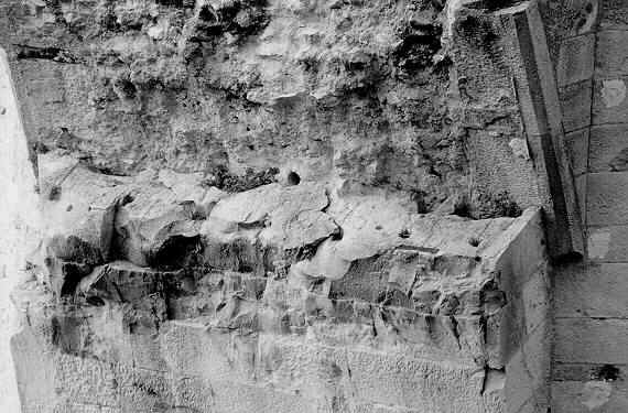
fig.18
– profile of the cornice at the starting point.
9.4
Spandrel stone assemblage
Spandrel
walls were made in ordinary ashlar masonry work with thin mortar joints. On top side of
the spandrels, across the joints, it was placed a single row of cramps approximately
located along the longitudinal axe of the stone elements, but variability of this
parameter was quite high being also related to the ashlars thickness dimensions. Stone
block rows were sometimes assembled with an imperceptible gradient, may, be due to
ordinary constructive imperfections or to due to optimisation of the connection with the
load bearing arch (as it has been noted by Mr.Bessac).
fig.19
– axonometric cut view showing the spandrel stones; on the right: plan view and
axonometric scheme.
assembling procedure:
- slots were carved over each stone block across the joints;
- for each joint two slots were carved (one per side) and joint was in the middle;
- between two twin-slots, located on the opposite sides of the joint, a trace was carved
to host the thickness of the cramp and to avoid any interference with the thickness of the
joints with above stone elements.
- once the spandrel stones were correctly placed on site, the cramps could be applied by
pouring melted lead in the slots;
technical observations:
- slots were slightly widen at the bottom to avoid untying;
- slots were not polished but perfectly cleaned;
- slots were of rectangular section as the cramps edges that were supposed to be inserted;
- cramp positions depended only on the position of the joint to be connected;
- one row of cramps was provided for each joint;
- cramps were of rectangular section profile with extreme edges widen by hammering, to
avoid untying; cramps were made in hand forged iron;
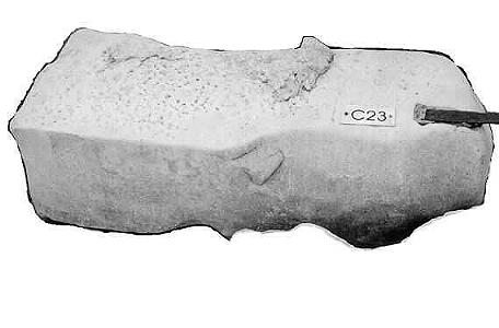
fig.20
– a spandrel block resumed from river waters; none of these blocks have been found
still assembled after destruction, may be due to the weaker connection with cramps and
dowels (compared to the one used for the vault).
criteria and dimensions:
- cramps divided the spandrel stone thickness in two equal
parts;
- the side cramps positioning criteria was quite simple: one cramp per joint of similar
dimensions;
- cramps sizes were slightly variable with no apparent criteria: most probably because of
ordinary constructive imperfections:
- cramp length: cm 30-35
- cramp hooking-edges length: cm 6-8
- cramp height: cm 4-5
- cramp height (widen edges by hammering): cm 6-7
- cramp thickness: cm 0.5-1
- cramp thickness (thinner edges by hammering): cm 0.5-0.8
- cramps were quite straight and hosted in the carved traces;
- dimensions of the carved traces were as the cramp profile to be settled in;
- dimensions of the slots were quite close to the cramps dimensions; of course the slot
opening should have been wide enough to allow the entrance of the cramp widen edge;
- slots had their bottom widen in order that hardened lead would have avoided untying;
- slots depth was enough to be suitable for the cramp edge to get in it;
9.5 Upper cornice
assemblage
Upper
cornices were placed, on a mortar layer, over the spandrel walls, with high accuracy to
gain a direction that on top had to be tangent to the lower cornice, and at the same time,
cornices were jutting out from the spandrel walls profile to protect them from rain water.
Upper cornices were generally bigger than lower cornices, and may be for this reason, had
two rows of cramps instead of one. Moreover cornices were provided with slots, and related
channels, that were used to host the dowels of the parapets.
fig.21
– axonometric cut view showing the upper cornice stones; on the right: plan view and
axonometric scheme.
assembling procedure:
- slots for cramps were carved over each stone block across
the joints;
- for each joint four slots were carved, (two per side), and joint was in the middle;
- between each two twin-slots, located on the opposite sides of the joint, a trace was
carved to host the thickness of the cramp and to avoid any interference with the thickness
of the joints with above parapet elements.
- once the upper cornice stones were correctly placed on site, the cramps could be applied
by pouring melted lead in the slots;
- slots for dowels were prepared for the above parapet assembling; positioning was worked
out depending on joints;
- a short channel for lead pouring was carved from the dowel slot, inwards, for a length
that was enough to reach the parapet inner edge;
technical observations:
- both slots for cramps and dowels were slightly widen at the
bottom to avoid untying;
- slots were not polished but perfectly cleaned;
- slots for cramps were of rectangular section as the cramps edges that were supposed to
be inserted;
- slots for dowels were of square-rectangular section as the dowels that were supposed to
be inserted;
- cramp positions depended only on the position of the joint to be connected;
- two rows of cramps were provided for each joint;
- cramps were of rectangular section profile with extreme edges widen by hammering, to
avoid untying; cramps were made in hand forged iron;
- slot position for dowels was worked out depending on joint positions either of cornices,
either of parapets: positioning had to respect the minimum distances from the joints of
both parapet and cornice that had to be connected;
- channels were V shaped, not polished but perfectly cleaned;
criteria and
dimensions:
- cramps divided the upper cornice stones thickness in three
equal parts;
- the cramps positioning criteria was quite simple: two cramps per joint of similar
dimensions;
- cramps sizes were slightly variable with no apparent criteria: most probably because of
ordinary constructive imperfections:
- cramp length: cm 30-35
- cramp hooking-edges length: cm 6-8
- cramp height: cm 4-5
- cramp height (widen edges by hammering): cm 6-7
- cramp thickness: cm 0.5-1
- cramp thickness (thinner edges by hammering): cm 0.5-0.8
- cramps were quite straight and hosted in the carved traces;
- dimensions of the carved traces were as the cramp profile to be settled in;
- dimensions of the slots were quite close to the cramps dimensions; of course the slot
opening should have been wide enough to allow the entrance of the cramp widen edge;
- slots had their bottom widen in order that hardened lead would have avoided untying;
- slots depth was enough to be suitable for the cramp edge to get in it;
- dimensions of the dowel slots carved in the upper cornices were of the type of the
wider-slots found in the vault: they were remarkably bigger compared to the dowel size and
were not regularly and accurately shaped; dimensions depended on needed adjustments: in
the available samples cm1-2 more than the other slots, (carved in the parapets), have been
surveyed, even if variability is high;
- slots had their bottom widen in order that hardened lead would have avoided untying:
lateral sides were accurately inclined of about 5° (few samples available);
- slots depth for the dowel was about half of the dowel length; gradient of slots and of
dowels have been found in some cases but samples were not enough to work out a possible
criteria;
- position of the slot for the dowel was determined by the outer edge of the cornice: it
was the sum of the following dimensions: jutting out portions of the cornice plus half of
the parapet thickness;
- channels were V and U shaped, but it seems that in the cornices were more V shaped:
about cm2-2.5 wide and 1-1.5 depth. really very few samples are still available for
inspection, (most of them are still assembled);
- channels were long enough to connect the slot to the inner side of the parapet, being
the parapet assembled, to allow lead pouring: about cm 15-16; channel was not any longer
than the parapet edge, and this accuracy is quite strange and may be explained only if the
flooring were conceived at a lower level, (same of the cornice), and the channel had,
therefore, to be hidden: this may also be confirmed by the average low level of the
parapets;
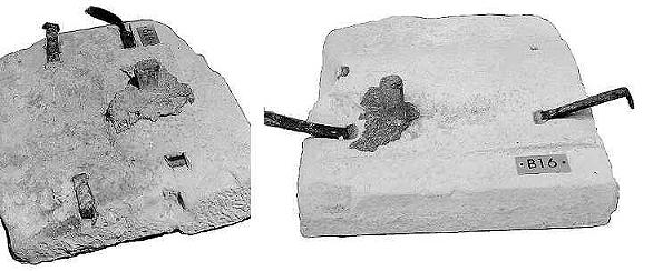
fig.22a
– some recovered upper cornice stones: two rows of cramps are clearly visible, (even
if some are missing), and the dowel(s) are still assembled with lead which has been
escaped in the surrounding area; position of the dowel is determined by the outer edge of
the cornice: jutting out portions of the cornices plus half of the parapet thickness;
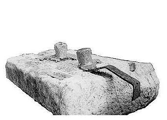 fig.22b – some recovered upper
cornice stones: two rows of cramps are clearly visible, (even if some are missing), and
the dowel(s) are still assembled with lead which has been escaped in the surrounding area;
position of the dowel is determined by the outer edge of the cornice: jutting out portions
of the cornices plus half of the parapet thickness;
channels had a gradient of about 45°, (in a plan
view), compared to the slots positions, and this may have been done for two reasons:
fig.22b – some recovered upper
cornice stones: two rows of cramps are clearly visible, (even if some are missing), and
the dowel(s) are still assembled with lead which has been escaped in the surrounding area;
position of the dowel is determined by the outer edge of the cornice: jutting out portions
of the cornices plus half of the parapet thickness;
channels had a gradient of about 45°, (in a plan
view), compared to the slots positions, and this may have been done for two reasons:
- to allow a better pouring of lead trough the channel that, being connected to the corner
of the slot, wouldn't have been obstructed by any of the dowel sides, and lead could have
winded, this way, correctly the dowel;
- to increase the channel's length and consequently its inclination towards the bottom, in
order to allow a better pouring of melted lead;
9.6 Parapets assemblage
Parapets
were assembled over the upper cornices with a mortar layer and with the dowels, that were
supposed to be previously mounted on the lower edge of the parapet, and inserted in the
slots of the upper cornices: the whole was linked by pouring melted lead in the purposely
carved channels over the cornices. On the top edge of the parapet some other cramps were
placed crossing the side joints, (linked as well with mortar). It seems that parapets,
getting to the top of the bridge, were purposely assembled slanting slightly outwards, may
be with the aim of obtaining an optical effect that could give the impression of a wider
footpath.
fig.23
– axonometric cut view showing the parapet stones assembled
assembling procedure:
- slots for cramps were carved over each stone block (top
edge) across the joints;
- for each joint two slots were carved (one per side) and joint was in the middle;
- between each two twin-slots, located on the opposite sides of the joint, a trace was
carved to host the thickness of the cramp and to allow cramp embankment in the stone;
- slots for dowels were prepared for the parapet assembling; positioning was worked out
depending on joints; slots for dowels were of the type of the smaller ones, and dowels
were accurately inserted in them pouring melted lead for anchoring the dowel to lower edge
of the parapet;
- once the parapet stones were correctly placed on site with dowels inserted in the gaps
of the cornices, lead could be poured in the channel for locking the two stone elements,
and the cramps on top could be applied by pouring melted lead in the slots;
technical observations:
- both slots for cramps and dowels were slightly widen at the
bottom to avoid untying;
- slots were not polished but perfectly cleaned;
- slots for cramps were of rectangular section as the cramps edges that were supposed to
be inserted;
- slots for dowels were of square-rectangular section as the dowels that were supposed to
be inserted;
- cramp positions depended only on the position of the joint to be connected;
- one row of cramps was provided for each joint over the thin top edge;
- cramps were of rectangular section profile with extreme edges widen by hammering, to
avoid untying; cramps were made in hand forged iron;
- slot position for dowels was worked out depending on joint positions either of cornices,
either of parapets: positioning had to respect the minimum distances from the joints of
both parapet and cornice that had to be connected;
fig.24
– front view, transversal section and axonometric view of the parapet
criteria and dimensions:
- cramps divided the upper thin edge of the parapet thickness
in two equal parts;
- the cramps positioning criteria was quite simple: one cramp, (of similar dimensions),
per joint;
- cramps sizes were slightly variable with no apparent criteria: most probably because of
ordinary constructive imperfections:
- cramp length: cm 30-35
- cramp hooking-edges length: cm 6-8
- cramp height: cm 4-5
- cramp height (widen edges by hammering): cm 6-7
- cramp thickness: cm 0.5-1
- cramp thickness (thinner edges by hammering): cm 0.5-0.8
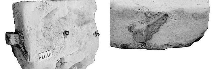
fig.25
– parapet recovered stones: dowel is still linked to the parapet and lead still
covers either the dowel either the area were the channel was: in second picture the shape
of the channel is clearly visible; (rings on the side of the parapet were used for fence
assembling;
cramps were quite straight and hosted in the carved
traces;
dimensions of the carved traces were as the cramp profile to be settled in;
dimensions of the slots for cramps were quite close to the cramps dimensions; of course
the slot opening should have been wide enough to allow the entrance of the cramp widen
edge;
slots had their bottom widen in order that hardened lead would have avoided untying;
slots depth was enough to be suitable for the cramp edge to get in it;
dimensions of the dowel slots carved in the upper cornices were of the type of the
smaller-slots found in the vault: dimensions of the smaller-slots were quite close to the
dowel dimensions (cm 1-2 of tolerance: globally not per each side); of course the slot
opening should have been wide enough to allow the entrance of the dowel head;
slots had their bottom widen in order that hardened lead would have avoided untying:
lateral sides were accurately inclined of about 5° (few samples available);
slots depth for the dowel was about half of the dowel length; gradient of slots and of
dowels have been found in some cases but samples were not enough to work out a possible
criteria;
position of the slot for the dowel was determined by the outer edge of the cornice: it
was the sum of the following dimensions: jutting out portions of the cornice plus half of
the parapet thickness;
dowels sizes were quite variable and with no apparent criteria: most probably because of
ordinary constructive imperfections:
- dowel section: square-rectangular
- dowel heads: (cm 4-5) × (cm 4-5); (also cm 6 has been found)
- dowel body section (midpoint): cm 3-4
- dowel length: cm 15-20; (high variation and difficult evaluation of still inserted
dowels);
dowels longitudinal section was continuos and variation from head size to body size was
reached gradually with a curved profile;
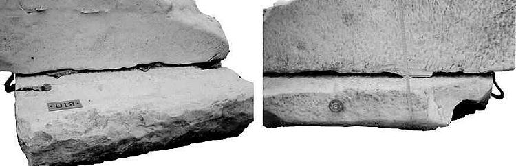
fig.26
– parapet and cornice still assembled: inner view and outer view (round stuff over
the cornice is a reference point, may be used during the 1982 survey).
9.7 Fence assemblage
Fences
were most probably assembled in a subsequent period to protect people from falling down;
but this may be not known for sure and will be subjected to further studies.
fig.27
– fences: details and orthogonal views of the fences and connections to the parapet;
Fence
was composed of three important elements:
- vertical bars with arrows on top (linked to parapets);
- horizontal bars (passing trough the vertical bars inside rings);
- bracing bars (connecting vertical bars to the outer side of the parapets).
Fences were made in forged iron and were assembled as here next
described:
- a couple of metal rings was linked to the inner side of the parapets: two rings for each
vertical bar;
- rings were applied with lead, which could be either melted and poured, either hardened
and hammered (as it was used for ancient fencing);
- once ring were correctly placed on-site, vertical bars with arrows were inserted in the
rings;
- along vertical bars there were three holes in the thickness of the bar and trough these
holes horizontal bars were placed (three rows);
- from the top of the vertical bar, right below the arrow, started a bracing bar which,
with a slight curvature, was connected to the parapet outer side with the same technique
described for the inner side.
fig.28 – fences: connecting details (connections between parapets and
fencing)
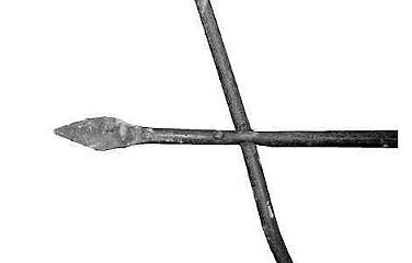
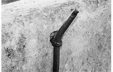
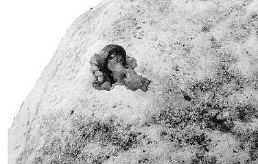
fig.29
– fences: vertical bar with top arrow; ring connection to the parapet (second and
third picture) |