9. Assembling techniques intro
GE
is grateful to LGA, that has contributed, trough its researches and observations to
determine some of the data here next reported. LGA additional research work has been
donated to UNESCO.
It should be underlined, anyhow, that notes
contained in this chapter are, in some cases, affected by the lack of source data:
recovered stones could not offer a number of samples wide enough to work out statistical
evaluations of the dimensions and to determine, with a margin of certainty, if the
described construction techniques were repeated identically in the whole structure.
For a better understanding of this chapter it is suggested to refer
to design drawings RE-06 and RE-07 in which schemes and detailed representations are
provided.
9.1
Bridge reinforced masonry
One
of the most interesting constructive characteristic of the former bridge was the
methodology of assembling the stones, performed with traditional mortar and additional
metal elements placed across joints with the aim of providing a sort of reinforcing system
which should have worked for the long lasting of the structure against river flows. Bridge
stone elements were linked, with the adjacent ones, trough special metal devices like
cramps and dowels that were anchored to stone blocks in purposely built slots in which it
was poured melted lead to lock the whole system. The ancient techniques used at the time
were undoubtedly advanced and a remarkable foreknowledge should be admitted: it seems that
they were aware of the fragile behaviour of stone to tensile stresses and that a sort of
implementation with a more ductile material like forged iron were a conscious device to
gain a more suitable and resistance structure. Nowadays we can observe that those metal
elements were not necessary for the stability and resistance of the bridge and that a good
mortar layer, with a periodical maintenance of the joints, would have ensured anyhow the
long lasting of the bridge. Nevertheless metal dowels may have contributed for the
resistance of the structure to eventual share forces due to horizontal thrusts of seismic
events and of river floods. Moreover cramps, over the extrados of the load bearing arch,
behaved as if metal ties were put around the vault, and they may have given a contribute
to face shifts and settlements of the ground and of the springers.
The stone arch structure stability is anyhow mostly related to the
shape and curvature of the arch, (it is commonly said that an arch, either collapses when
centering is dismantled, either lasts forever); while the stone arch structure resistance
is mostly related to the resistance of the construction materials to compression stresses.
fig.01
– axonometric cut view of the stone elements of the bridge.
Metal
strengthening devices were assembled with stones following accurate criteria, some of
which are clearly visible and understandable, but some others have required a more
detailed analysis and inquiry. These criteria have been quite difficult to be fully
determined, either for the ruined current condition of the bridge, either for the ranges
in which all the dimensions vary, that may wrongly lead to think that some choices had
been performed randomly and not trough a plan or a methodology.
In this chapter have been reported the results of the studies
concerning the assembling technique and the refine constructive method designed by an
architect that has left a really impressive example of the knowledge of the time.
9.2 Voussoirs assemblage
Being
the arch voussoirs the elements of the load bearing arch, and therefore the most important
portion of the bridge, many reinforcing devices were present to ensure efficient joint
connections.
To better understand how voussoirs were assembled,
it has to be pointed out the following:
- the load bearing arch was composed by 111 rows of voussoirs in a
thickness of cm395;
- each row could contain 2-5 voussoirs (average 3-4);
- rows of voussoirs were mounted from both side of the bridge;
- joints, among voussoirs belonging to one row, were shifted compared
to the preceding row, (as it happens in an ordinary masonry layout);
- a mortar layer was used to combine adjacent voussoirs, (as it happens
in an ordinary masonry work);
- additional metal elements were mounted across the joints.
- three different strengthening metal devices were used for the arch
stones: dowels, side cramps and extrados cramps;
metal elements, and purposely built carvings to host them, were of dimensions and sizes
quite variable in the bridge structure.
9.2.1 Dowels in the arch stones
Each
arch stone was linked to one or two voussoirs of the preceding row by one or more metal
dowels. Dowels were applied to the stone blocks in purposely carved slots, (holes), and
melted lead was poured in the slots to connect metal and stone elements.
fig.02
– front view of the arch during the assembling with details of the arch stones and
dowels;
assembling procedure:
- arch stone already assembled is defined as A-1° and arch stone to be mounted is defined
as A-2°;
- a slot was carved on one side of the stone that was supposed to be mounted (A-2°);
- this slot was precise and accurately cut: wide enough to host the dowel;
- the dowel was applied to the stone that was supposed to be mounted (A-2°);
- presumably still off-site, melted lead was poured as connection among dowel and stone;
- a wider slot was carved on the built-in stone (A-1°), in a position that was matching
with the dowel mounted over stone A-2°;
- a channel was carved on the built-in stone (A-1°) going from the slot to the extrados;
- the new stone, to be mounted (A-2°), was placed on site and its dowel inserted in the
slot of the stone of the preceding row (A-1°); a mortar layer was interposed among
joints;
- melted lead was poured trough the channel to fill the slot and to connect firmly dowel
to the built-in stone (A-1°);
- the above procedure was identical even if more dowels and slots were used;
technical observations:
- slots were slightly widen at the bottom to avoid untying;
- slots in the built-in stones (A-1°) were wider to allow the positioning and adjusting
of the new stone (A-2°), and matching of the dowel with related slot;
- slots were of square/rectangular section as the dowels that were supposed to be
inserted;
- slots were not polished but perfectly cleaned;
- dowel position should have been planned knowing all the joint positions of both of the
rows to be connected, to avoid positioning of dowels next or over the joints;
- channels should have been protected to avoid their obstruction with mortar;
- channels were V shaped or U shaped, not polished but perfectly cleaned;
- lead, while melted, in many cases, has escaped from the slot going all around in the
joint thickness and filling other gaps;
- dowels were of square-rectangular section profile with heads widen by hammering, to
avoid untying; dowels were made in hand forged iron;
- top arch stone row was presumably without dowels to allow correct insertion of key
stones;
fig.03
– two adjacent rows (side open view); top image: built-in row; below image: row to be
assembled
It has to be underlined that the assembling
of the voussoirs was quite a delicate working stage since voussoirs had to be chosen and
prepared following the below mentioned requirements:
- each row had to be composed of 2-5 voussoirs with similar front faces, (tolerances were
included between cm 0.5 and 2.5 - only sometimes till cm 3.5);
- each row had to be cm 395 of length;
- adjacent rows had to have their joints shifted (as in ordinary masonry);
- dowels positioning had to respect the minimum distances from the joints of both the rows
that were connected;
From the above it should be clear that stones were not randomly chosen
even if the rows were all different and their front faces were of remarkably different
sizes and shapes.
Undoubtedly voussoirs were well linked one to each other, if we think
that, even after the destruction of the bridge, most of the recovered arch stones are
still assembled in huge blocks.
criteria and dimensions:
- dowels were positioned at about cm40, from the extrados (which is half way between
extrados and intrados); this matter may have been subjected to considerable variations at
the springers: two anomalous samples have been surveyed on-site;
- dowel positioning criteria are represented in figure here below reported; those criteria
were aimed at preserving the integrity of the stones by placing the dowels not too close
to the stone edges which would have been weakened by the carved slots;
- dowels sizes were quite variable and with no apparent criteria: most probably because of
ordinary constructive imperfections:
- dowel section: square-rectangular
- dowel heads: (cm 4-5) × (cm 4-5); (also cm 6 has been found)
- dowel body section (midpoint): cm 3-4
- dowel length: cm 15-20; (high variation and difficult evaluation of still inserted
dowels);
- dowels longitudinal section was continuos and variation from head size to body size was
reached gradually with a curved profile;
fig.04 – dowels positioning criteria (plan
view): voussoir with more dowels: a>cm17 b>cm37; voussoir with one
dowel: c˜d/2; edge voussoir: e˜cm37.
dimensions of the smaller-slots, (in stone
A-2°), were quite close to the dowel dimensions (cm 1-2 of tolerance: globally not per
each side); of course the slot opening should have been wide enough to allow the entrance
of the dowel head;
- dimensions of the wider-slots, (in stone A-1°), were remarkably
bigger compared to the dowel size and were not regularly and accurately shaped; dimensions
depended on needed adjustments: in the available samples cm1-2 more than the other slots
have been surveyed, but variability is high;
- slots had their bottom widen in order that hardened lead would have
avoided untying: lateral sides were accurately inclined of about 5° (few samples
available);
- slots depth was about half of the dowel length, and, in the first stone in which it was
inserted (A-2°), the dowel-head was touching the bottom of the slot in a way that
sometimes it was not covered by melted lead; gradient of slots have been found in some
cases but samples were not enough to work out a possible criteria;
fig.05
– plan view (section): a detail of a dowel
channels were V and U shaped, but it seems that in
the voussoirs were more U shaped: about cm2-2.5 wide and 1-1.5 depth. really very few
samples are still available for inspection, (most of them are still assembled);
channels were long enough to connect the extrados to the slot: about cm 40.
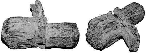 fig.06a
– some recovered dowels winded by lead; in the first sample it is possible to note
the different size and type of lead cover depending on the different slots; in the second
sample it is possible to note the portion of lead pertaining to the channel; in third and
fourth samples the dowel is half visible; in fourth sample the lead has spread all around
in the joint.
fig.06a
– some recovered dowels winded by lead; in the first sample it is possible to note
the different size and type of lead cover depending on the different slots; in the second
sample it is possible to note the portion of lead pertaining to the channel; in third and
fourth samples the dowel is half visible; in fourth sample the lead has spread all around
in the joint.
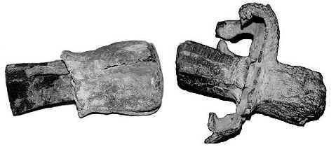
fig.06b
– some recovered dowels winded by lead; in the first sample it is possible to note
the different size and type of lead cover depending on the different slots; in the second
sample it is possible to note the portion of lead pertaining to the channel; in third and
fourth samples the dowel is half visible; in fourth sample the lead has spread all around
in the joint.
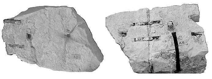 fig.07
– some recovered stones: the first one is stone A2 and the second is stone A8: it is
possible to see on both of them the carved channels; in the third sample a very peculiar
case has been found: the slot was really close to the edge and among the side cramps:
channel (even if scarcely visible) had a gradient (about 30°) in order not to interfere
with the cramps.
fig.07
– some recovered stones: the first one is stone A2 and the second is stone A8: it is
possible to see on both of them the carved channels; in the third sample a very peculiar
case has been found: the slot was really close to the edge and among the side cramps:
channel (even if scarcely visible) had a gradient (about 30°) in order not to interfere
with the cramps.
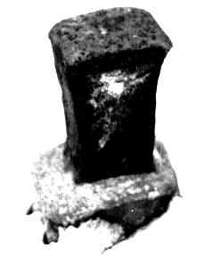
fig.08
– a dowel still inserted in the stone slot: it is visible its curved profile and its
widen head presumably obtained by hammering (hand forging);
9.2.2 Side cramps in the arch stones
Adjacent
voussoirs of each row were connected with double side cramps crossing the joints; even in
this case cramps were linked to the stone by melted lead, poured in purposely built slots.
Side cramps were quite regular, of similar shape and size and they had not so many
variations along the load bearing arch.
assembling procedure:
- slots were carved over the side of each stone block across
the joints among two adjacent voussoirs;
- for each joint four slots were carved, (two per side), and joint was in the middle;
- slots were carved only on the side of the row that looked towards the keystone;
- between two twin-slots, located on the opposite sides of the joint, a trace was carved
to host the thickness of the cramp and to avoid any interference with the thickness of the
joints among adjacent rows.
- once the voussoirs were correctly placed on site, the side cramps could be applied by
pouring melted lead in the slots;
fig.09
– axonometric view of the load bearing arch during the assembling stage;
technical observations:
- slots were slightly widen at the bottom to avoid untying;
- slots were not polished but perfectly cleaned;
- slots were of rectangular section as the cramps edges that were supposed to be inserted;
- cramp positions depended only on the position of the joint to be connected;
- two rows of cramps were provided for each joint (presumably to avoid rotations);
- lead pouring was quite easy for all the rows of the arch, special devices might have
been used for the rows close to the key stone because of the gradient of the slots;
similar problems were probably present also for the channels of the dowels: there, the
work was much easier at the top of the arch, (because of gravity), than at the springer
where the channels had a very low gradient (almost horizontal);
- cramps were of rectangular section profile with extreme edges widen by hammering, to
avoid untying; cramps were made in hand forged iron;
- top arch stone row was presumably without cramps to allow correct insertion of key
stones;
fig.10
– plan view of a portion of the load bearing arch: side cramps are visible crossing
the inner joints;
criteria and dimensions:
- the two side cramps divided the arch stone height in three
equal parts: the distance from upper cramps to the extrados was approximately equal to the
distance among the cramps, and equal to the distance among lower cramp and intrados: about
cm 25-27; this matter may have been subjected to considerable variations at the springers,
(two anomalous samples have been surveyed on-site);
- the side cramps positioning criteria was quite simple: two cramps per joint of similar
dimensions;
- cramps sizes were slightly variable with no apparent criteria: most probably because of
ordinary constructive imperfections:
- cramp length: cm 30-35
- cramp hooking-edges length: cm 6-8
- cramp height: cm 4-5
- cramp height (widen edges by hammering): cm 6-7
- cramp thickness: cm 0.5-1
- cramp thickness (thinner edges by hammering): cm 0.5-0.8
- cramps were quite straight and hosted in the carved traces;
- dimensions of the carved traces were as the cramp profile to be settled in;
- dimensions of the slots were quite close to the cramps dimensions; of course the slot
opening should have been wide enough to allow the entrance of the cramp widen edge;
- slots had their bottom widen in order that hardened lead would have avoided untying;
- slots depth was enough to be suitable for the cramp edge to get in it;
9.2.3 Extrados
cramps in the arch stones
Extrados
cramps were located over the extrados of the load bearing arch: there were five rows of
cramps that ran in parallel directions following the curved profile. The extrados cramps
acted like tying chains, or at least they were conceived with this purpose, being one
adjacent to each other. These cramps were different from all the others that have been
found in the bridge stone structure, because they were dimensioned depending exclusively
on the arch stone measures: where one cramp ended, the other started, sharing the same
stone-slot to allow continuity of the tying action.
fig.11
– axonometric view of the load bearing arch during the assembling stage; extrados
cramps are visible;
assembling procedure:
- slots were carved on the extrados of the voussoirs, following five parallel directions
which ran at an equal distance;
- side joints of the voussoirs were carefully avoided, and because of this, sometimes the
cramps direction slightly bent following a sort of a sinuous path;
- slots were carved approximately in the axe of each arch stone row;
- mostly for what concern the outer "chains" of cramps, (where lower cornices
were supposed to be mounted), a sort of rough smoothing of the extrados was performed, and
traces were carved to host the thickness of the cramps and to avoid any interference with
the above stone elements to be assembled; for the inner chains of cramps this was
partially performed;
- once the voussoirs were correctly placed on site, the extrados cramps could be applied
by pouring melted lead in the slots;
- each slot was shared by two edges of adjacent cramps;
- cramps were slightly curved and adapted to the arch extrados profile; might have been
also slightly hammered on site;
fig.12
– plan view of a portion of the load bearing arch: extrados cramps are visible;
fig.13
– a detail of the previous image;
technical observations:
- slots were slightly widen at the bottom to avoid untying;
- slots were not polished but perfectly cleaned;
- slots were of rectangular section as the cramps edges that were supposed to be inserted;
- cramp positions followed mainly five parallel directions almost regardless of the stones
that were connected, (except for the position of the joints that were accurately avoided);
- five rows of cramps were provided as tying chains;
- lead pouring was quite easy for all the rows of the arch, special devices might have
been used next to the arch springers;
- cramps were of rectangular section profile with extreme edges widen by hammering, to
avoid untying; cramps were made in hand forged iron;
- cramps were all of different sizes depending on the voussoir dimensions, (different one
to each other);
- cramps had to be slightly bent to match the extrados profile;
fig.14
– cut view: extrados cramps
criteria and dimensions:
- the side cramps positioning criteria was quite simple: the
extrados cramps were assembled in five parallel chains, and distance among them was
approximately cm80; the chains of cramps, located closer to the vault edges, were at a
distance of about cm37 from the outer profile;
- extrados cramps had their slots approximately in the middle of the voussoirs;
- the slots were wide enough to host two adjacent cramps edges; of course the slot opening
should have been wide enough to allow the entrance of the cramp widen edges;
- cramps were all of different lengths, being related to the voussoirs dimensions; other
cramp sizes were variable with no apparent criteria: most probably because of ordinary
constructive imperfections:
- cramp length: variable
- cramp hooking-edges length: cm 6-8
- cramp height: cm 4-5
- cramp height (widen edges by hammering): cm 6-7
- cramp thickness: cm 0.5-1
- cramp thickness (thinner edges by hammering): cm 0.5-0.8
- cramps were considerably bent and hammered to match the extrados profile; they were
hosted in carved traces;
- dimensions of the carved traces were as the cramp profile to be settled in;
- slots had their bottom widen in order that hardened lead would have avoided untying;
- slots depth was enough to be suitable for the cramp edges to get in it;
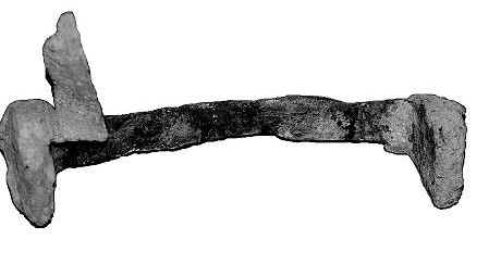
fig.15a
– cramps with their edges still covered by lead
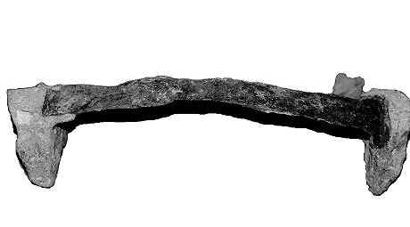
fig.15b
– cramps with their edges still covered by lead
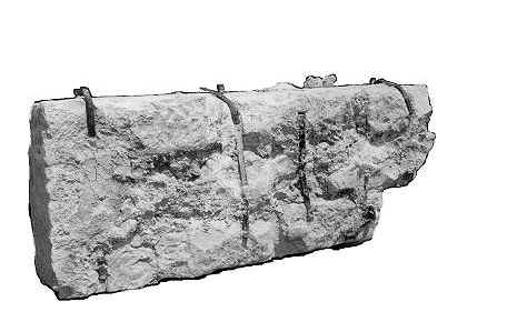
fig.16a
– view of portion of the vault (extrados side): extrados cramps are visible;
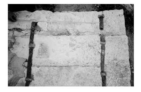
fig.16b
– view of portion of the vault (extrados side): extrados cramps are visible; |